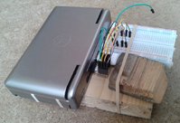
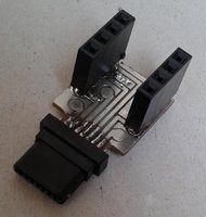
I drew a new breakout board to fit ED's EXT connectors. This one is focussed on the GPIO pins, with pads for the TV/audio just to help me check for shorts. (The TinyBoB was designed to be suitable for making TV-out cables too, but we have the official TV-out cables now.)
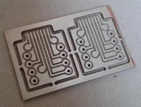
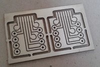
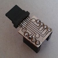
These are milled PCBs, with extra copper on the unused areas, and no plated holes or solder resist. Trying to solder sockets onto that was a bad idea: harder than actually soldering the EXT connector. I tested all the combinations of tracks for shorts, and pushed solder around until it came up clear. You can see my dodgy soldering in the pictures. I'll probably put some Araldite on it once I've checked that all the pins are connected. For now, the Pandora and a piece of breadboard are strapped onto a block of wood so the connector doesn't have much force on it.
The strips of copper on the bottom edges were not useful. I'd probably remove them in the next version.
The board was nominally 0.8mm thick, but came out at 1.0mm, which is about right (lucky for me). I might get some boards made sometime at a regular PCB manufacturer, for the solder resist and plated holes. I wouldn't really want to solder another one like this. (Milling might still be useful for something like the IR project, where there would be a small number of components, all on wires. I don't know which EXT pin would make the best output yet.)
----
Following the instructions here, I configured uart2_cts as a GPIO output and switched it on and off a few times
http://boards.openpandora.org/topic/4497-talking-to-the-gpios-on-the-ext-connector/?p=195457
http://bbfordummies.blogspot.co.uk/2009/07/1.html
Is there information somewhere about configuring UART parameters?
And has anyone done anything with PWM? (In the linked thread, Notaz said PWM "Can be enabled as well but they might be tricky to program, as it's a function of general purpose timers, and those can sometimes be in use for other things" and "you'd probably need to write a kernel driver to program the timer and get that PWM functionality".)


ext_5_designspark-pcb.zip
These are milled PCBs, with extra copper on the unused areas, and no plated holes or solder resist. Trying to solder sockets onto that was a bad idea: harder than actually soldering the EXT connector. I tested all the combinations of tracks for shorts, and pushed solder around until it came up clear. You can see my dodgy soldering in the pictures. I'll probably put some Araldite on it once I've checked that all the pins are connected. For now, the Pandora and a piece of breadboard are strapped onto a block of wood so the connector doesn't have much force on it.
The strips of copper on the bottom edges were not useful. I'd probably remove them in the next version.
The board was nominally 0.8mm thick, but came out at 1.0mm, which is about right (lucky for me). I might get some boards made sometime at a regular PCB manufacturer, for the solder resist and plated holes. I wouldn't really want to solder another one like this. (Milling might still be useful for something like the IR project, where there would be a small number of components, all on wires. I don't know which EXT pin would make the best output yet.)
----
Following the instructions here, I configured uart2_cts as a GPIO output and switched it on and off a few times
http://boards.openpandora.org/topic/4497-talking-to-the-gpios-on-the-ext-connector/?p=195457
http://bbfordummies.blogspot.co.uk/2009/07/1.html
Is there information somewhere about configuring UART parameters?
And has anyone done anything with PWM? (In the linked thread, Notaz said PWM "Can be enabled as well but they might be tricky to program, as it's a function of general purpose timers, and those can sometimes be in use for other things" and "you'd probably need to write a kernel driver to program the timer and get that PWM functionality".)


ext_5_designspark-pcb.zip
Attachments
Last edited by a moderator:


