Talking to the GPIO's on the EXT-connector


panik

Member
Joined
Sep 21, 2008
Messages
187
Age
53
Location
Netherlands
Now that we have the ext-connectors, we want to be able to talk to the GPIO's (yes, we do!). In the Hacker's manual there's a warning about the voltage levels on the GPIO pins on the ext-connector:

*** NOTE – All digital pins on this connector are 1.8V logic and must be level shifted if they need to be interfaced to a higher/lower voltage system. Failure to do so could result in permanent damage to these pins on the OMAP3530, rendering them inoperable or even creating a short circuit inside the chip.
What's needed is some way to change the voltages in and out of the pins to the voltage you want use on the pins. On the "official" breakoutboard (picture and schematic) there's a TXB0104 level converter that handles this for 4 of the pins (the other 2 go directly in the maxim rs232-chip). I wanted more flexibility, so I needed the TXB0106, that has 6 of these 'converters' for all 6 GPIO's (TXB0106 datasheet).


After receiving the excellent TinyBoB's and an ext-connector from peca yesterday, I started soldering it up. The TXB0106 comes in a TSSOP16-package, which is a PITA to handle and solder to a converter-board. It took 2 attempts, but I'm very happy with the results from the second try.


Here's what it looks like after a couple of hours of soldering:
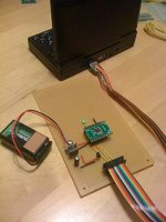

txb0106_1.jpg


From the pandora down to the board (follow the cable), we see:


- My trusty Pandora.


- ext-connector.


- TinyBoB.


- 14-pins flatcable.


- 14 pins IDC-connector.


- 1.8 Volt voltage regulator (needs 2 1uF caps, didn't have them so I left them out).


- (to the left) 5.0 Volt voltage regulator with 2 supporting caps and 'idiot-diode'.


- 9 Volt battery.


- The TXB0106 voltage level converter on a SSOP20-PDIP converter board.


- Green LED for testing purposes.


There are 3 GPIO's going to the TXB0106 at the moment (yellow wires). One of them has a physical LED connected on the 'other end'. I just measured voltages on the rest of the pins.


Following these instructions for accessing the GPIO's on the beagleboard, I have some serious blinkylight action going on (slightly adjusted code posted below).


Code:
#!/bin/sh

# Blinkylights on the Pandora GPIO's

# Use 145, 147, 144, 166, 146 or 165


GPIO=$1


cleanup() { # Release the GPIO port

  echo $GPIO > /sys/class/gpio/unexport

  exit

}


# Open the GPIO port

#

echo $GPIO > /sys/class/gpio/export 


trap cleanup SIGINT # call cleanup on Ctrl-C


# Blink forever

while [ "1" = "1" ]; do

  echo "high" > /sys/class/gpio/gpio$GPIO/direction 

  sleep 1

  echo "low" > /sys/class/gpio/gpio$GPIO/direction  

  sleep 1

done


cleanup # call the cleanup routine


Here's the result running the script on the different GPIO's, following the description of the pin-out image of the ext-connector in the hacker's manual:


(1) UART2_RTS/GPIO_145/PWM10


Works as expected. Blinkylights!


(2) UART2_RX/GPIO_147/PWM8


Works as expected. Blinkylights!


(3) UART2_CTS/GPIO_144/PWM9


Voltmeter shows 'blinking' at -1.8 to 0 Volts. Negative voltages. What's up with that? (serious question, is this done in software somewhere?)


(4) UART3_TX/GPIO_166


Voltmeter shows 0 Volt. Script running or not. No blinky.


Pandorawiki mentions "In the 2.6.27 Kernel UART3 is /dev/ttyS0". I need to test this.


(5) UART2_TX/GPIO_146/PWM11


Works as expected. Blinkylights!


(6) UART3_RX/GPIO_165


Voltmeter shows +1.8 Volt. Script running or not. No blinky.


Pandorawiki mentions "In the 2.6.27 Kernel UART3 is /dev/ttyS0". I need to test this.


I wanted to feed the 1.8V voltage regulator from the 3V-line (2.8V actually) coming from the Pandora, but this didn't work as expected. I ended up with less than 1 Volt coming from the regulator. It now runs on the 5V coming from the battery and the 5V voltage regulator. I need to do more testing, to see what happened.


Plans for the future are adding a 3.3 Volt voltage regulator, and make that 'user-selectable', so you can choose between 5V and 3.3V and drive your own additional circuits from there. When I can get the 1.8V from the Pandora, users will also be able to run the breakoutboard in a 'selfpowered mode' where the GPIO's are driven from the 3V (2.8V) from the Pandora. Then the battery and extra voltage regulators can be left out. I plan on drawing the schematics and board in Eagle, and send it off to a PCB-service somewhere (never done that before, though. It will probably take some tries).


The idea is that there will be another 14-pins IDC connector on the other end of the board, that has the same pinout as the one that's coming in, but this time with the GPIO's and power-line at the voltage of your choice.


Idea's you have, flaws you spot, info you're willing to share, I would love to hear your thoughts.
 
Last edited by a moderator:
Awesome job!!


That script will be very useful for my own project once i start using the ext connector instead of the usb.


Thanks for sharing!
 
The idea is that there will be another 14-pins IDC connector on the other end of the board, that has the same pinout as the one that's coming in, but this time with the GPIO's and power-line at the voltage of your choice.


Idea's you have, flaws you spot, info you're willing to share, I would love to hear your thoughts.


I like the idea. If you were packaging this as a GPIO voltage converter circuit though, wouldn't it make more sense to accept an input voltage from the destination circuit, (5v or 3.3v) and convert to whichever voltage is presented rather than putting a battery and regulator on this one? or am I missing something here? (it has been a while since I studied electronics and even then it was just the basics...)


- Neelix
 
I need to know how to add buttons to the Pandora via GPIO pins.


Is it as simple as connecting GND to one of the GPIO pins?


Can such a button be mapped to a keyboard button (or L2 R2 Button) with a simple script?


Thanks!
 
Last edited by a moderator:
Awesome job!!


That script will be very useful for my own project once i start using the ext connector instead of the usb.


Thanks for sharing!
Thanks, I was expecting you. :)


The script is basically writing to (or reading from) 'files' in /sys/class/gpio/. It should be just as easy to do in C/C++, even though I don't know if that's the best way to do it. The word 'kernel' pops up a lot when reading about GPIO's in general. I don't know enough about that stuff.

I like the idea. If you were packaging this as a GPIO voltage converter circuit though, wouldn't it make more sense to accept an input voltage from the destination circuit, (5v or 3.3v) and convert to whichever voltage is presented rather than putting a battery and regulator on this one? or am I missing something here? (it has been a while since I studied electronics and even then it was just the basics...)
Ah, yes. That does make sense and it was actually the original plan. I was hoping to get the power from the pandora for the 1.8V reference voltage the TXB0106 needs. Since this failed (don't know why, it should work) I needed the 5V voltage regulator on the board. This triggered the idea to have supply voltage on the board and add a 3.3V regulator as well.


So yes, I might go 'back' to what you're saying. :)


It should be possible to implement it so that you can use the regulators and battery if you want to, and don't use them if you don't need to. Even go as far as not soldering them on and still have a usable board. Maximum input of the TXB0106 is 5.5V by the way, so you can't go too wild.


Also, the prototype I soldered would be exactly the same. :)

I need to know how to add buttons to the Pandora via GPIO pins.


Is it as simple as connecting GND to one of the GPIO pins?


Can such a button be mapped to a keyboard button (or L2 R2 Button) with a simple script?


Thanks!
The instructions for the beagleboard I mentioned also describes how to poll input.


If I understand them correctly, you'll want to echo both the word "in" and "high" to the "direction", so you'll get a '1' when you don't press the button (pin is pulled up), and a '0' when you do press the button, since you're pulling it to ground. But I don't know enough about this /sys/class/gpio thing to say that it is possible.


I think the stuff you echo to the "direction" overwrites what's already in it, so I have no idea how to create a pulled-up input on the Pandora. Still, interesting.


Edit: Ah, there's also a 'value' entry of course, that might do something. Needs testing.
 
Last edited by a moderator:
For UART3 pins, you need to switch them from uart mode to GPIO mode in pin mux. This would currently require recompiling u-boot, I'll think about including controls for this to next hotfix. Maybe add regulator voltage control too.


Would you test this stuff for me? I was reluctant to add this stuff until someone actually start using this.


Don't know what's wrong with UART2_CTS though, it's set up exactly like others and should just work. Maybe it's a bad connection or some defect on your pandora board itself.
 
Last edited by a moderator:
For UART3 pins, you need to switch them from uart mode to GPIO mode in pin mux. This would currently require recompiling u-boot, I'll think about including controls for this to next hotfix. Maybe add regulator voltage control too.
Actually, I was quite happy to learn that there's an active UART on the pins. But having control over their functionality would be even better! How about the PWM on those 'UART2' pins?


With "regulator voltage control", you mean you have control over the voltage of the power-pin on the ext-port? If that could be 1.8 Volt, there's no need for any other component on the board but the TXB0106 itself. It would make things a lot easier. Also more dangerous, when there's more than 1.8 Volt on the pins and there's hardware connected. Or I understand it wrong.

Would you test this stuff for me? I was reluctant to add this stuff until someone actually start using this.
I'd be honored, Sir. Thank you very much!

Don't know what's wrong with UART2_CTS though, it's set up exactly like others and should just work. Maybe it's a bad connection or some defect on your pandora board itself.
I'll test some more and give it some time. Who knows? I hope it's just me being an idiot. That wouldn't be a first.
 
Actually, I was quite happy to learn that there's an active UART on the pins. But having control over their functionality would be even better! How about the PWM on those 'UART2' pins?
Can be enabled as well but they might be tricky to program, as it's a function of general purpose timers, and those can sometimes be in use for other things.

With "regulator voltage control", you mean you have control over the voltage of the power-pin on the ext-port? If that could be 1.8 Volt, there's no need for any other component on the board but the TXB0106 itself. It would make things a lot easier. Also more dangerous, when there's more than 1.8 Volt on the pins and there's hardware connected. Or I understand it wrong.
Yeah it's software controllable regulator with 5 possible voltages: 1.5, 1.8, 2.5, 2.8 and 3.0V.


But there's a catch: both bootloaders switch this to 2.8V as our debug boards use 2.8V, this is to debug early boot stuff. The control would only be useful in kernel, which loads quite a bit later, so you'd get 2.8V for some seconds after each reboot which is easy to forget. Need to think more about this.
 
I need to know how to add buttons to the Pandora via GPIO pins.


Is it as simple as connecting GND to one of the GPIO pins?


Can such a button be mapped to a keyboard button (or L2 R2 Button) with a simple script?


Thanks!

If you just want L2/R2, there's no need to use these GPIOs. L2/R2 already exist on the board (and even in the input tester in the OS).


They only need to be soldered to the pads on the PCB.
 
If you just want L2/R2, there's no need to use these GPIOs. L2/R2 already exist on the board (and even in the input tester in the OS).
They only need to be soldered to the pads on the PCB.
Nardela trying to avoid soldering into Pandora. He like to make some substitution - external add-on - that could be used as L2/R2 + some other functions (USB HUB, TV-out, more buttons...) (IIRC :) )
 
Nardela trying to avoid soldering into Pandora. He like to make some substitution - external add-on - that could be used as L2/R2 + some other functions (USB HUB, TV-out, more buttons...) (IIRC :) )

Actually, it'd be cool if we (the royal 'we'; i.e the community) could design a simple pcb that would take a couple of 9-pin d-sub joystick/pads, i.e Atari 2600/C64/Megadrive/Amiga, etc. through the EXT connector. Not looked closely enough at these threads or the wiki to see if the hardware could support that.... <_<


Of course the emulators would need updating to support them, too.... Imagine 2-player Rainbow Islands with real joysticks or IK+, Kikstart II... drool!
 
Last edited by a moderator:
Not looked closely enough at these threads or the wiki to see if the hardware could support that.... <_<

you'd need to convert it to serial and use the uart, or at least multiplex it in, joystick ports are just direct lines to the buttons and axes (hence the limit of 4 axis, 4 buttons or whatever it is)

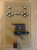
I once used an ATMega8 microcontroller with the Obdev V-USB library to create a USB-HID joystick. The Pandora instantly recognized it (no drivers needed), and I've been playing some Metal Slug with it.


usb-hid17.jpg


It wasn't 'simple', but most emulators recognized it as a regular joystick. I soldered tactile buttons on the board as a D-pad, start, select, abxy, and 2 shoulder-buttons. In theory it's possible to use up to 17 buttons, 6 of which can be analog (ATMega8 restrictions). These tactile buttons should of course be replaced by some serious arcade buttons/joysticks or a 9-pin d-sub to hook up old-school joysticks. I think that should work.


However, that's another project. :)


In the mean time, I've been trying to talk to UART3. I can't even get a loopback test going, by connecting the RX to the TX pin. I should see back what I type in minicom, but no cigar. Not even close.


However, every now and then, some gibberish appears. Could these be kernel messages that are being sent to /dev/ttyS0 perhaps? If so, is there a way to turn that off?


Running hotfix 5. 'uname -r' says '2.6.27.46'. Using /dev/ttyS0, whatever baudrate, 8N1, no flow control.
 
Last edited by a moderator:
If you just want L2/R2, there's no need to use these GPIOs. L2/R2 already exist on the board (and even in the input tester in the OS).
They only need to be soldered to the pads on the PCB.
There are many reasons that this is not a viable option for most of the community.


*The board needs to be soldered to. Voiding the warranty (AAUI)


*Soldering is well beyond the comfort level of many if not most owners.


*Sending away the Pandora to have this mod done by someone else would be problematic in many ways (cost, time, safety).


*The casing of the Pandora would have to be modified.


*The mod would either have to be permanent or some method disconnecting and reconnecting the hardware would have to be developed.


Is it possible to use easily use pins on the EXT connector as buttons?
 
Any chance you could tell me in detail how to do this?

not without having to do it myself :p


gpios can be accessed from userland in the same way you would on any linux system (look it up), on the hardware side, it's just a push to make (or break) switch, and a pull up (or down) resistor depending on what configuration you want to give the gpio
 
Actually, I was quite happy to learn that there's an active UART on the pins. But having control over their functionality would be even better! How about the PWM on those 'UART2' pins?
Can be enabled as well but they might be tricky to program, as it's a function of general purpose timers, and those can sometimes be in use for other things.
Once we can talk to a microcontroller over UART, we'll not only have PWM but also ADC, I2C, SPI etcetera, along with a virtually unlimited amount of GPIO's. So no problem there. :)

With "regulator voltage control", you mean you have control over the voltage of the power-pin on the ext-port? If that could be 1.8 Volt, there's no need for any other component on the board but the TXB0106 itself. It would make things a lot easier. Also more dangerous, when there's more than 1.8 Volt on the pins and there's hardware connected. Or I understand it wrong.
Yeah it's software controllable regulator with 5 possible voltages: 1.5, 1.8, 2.5, 2.8 and 3.0V.


But there's a catch: both bootloaders switch this to 2.8V as our debug boards use 2.8V, this is to debug early boot stuff. The control would only be useful in kernel, which loads quite a bit later, so you'd get 2.8V for some seconds after each reboot which is easy to forget. Need to think more about this.
It'll probably be best to just use the supply voltage from the outside circuit to power the 1.8V regulator. Then we can simply leave the positive power-pin from the Pandora alone. Still, pretty neat it's controllable.

[...] the royal 'we'; i.e the community [...]
This applies to my use of the word "we" as well. :)
 
Back
Top