FTDI


HelenF

Very Active Member
Joined
Jun 22, 2013
Messages
615
Location
UK
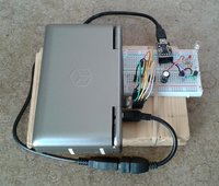
I'm playing with one of these at the moment:

http://www.ebay.co.uk/itm/281251283409

The default mode is as a UART. I was able to change the baud rate and the number of bits per character using the termios interface (as I was doing with the UARTs on the EXT connector earlier).

Libftdi compiled easily in CodeBlocks, though without the EEPROM part (for which it was missing some dependency, I forget what). Running the programs as root is awkward because it loses LD_LIBRARY_PATH: "sudo chmod o+w -R /dev/bus/usb" let them run as regular user afterwards, for the current connection. I heard the proper way is to make a udev rule, but I don't really understand that yet.

The bitbang mode seemed interesting. The FT232R datasheet says it has a 128 byte FIFO buffer for storing bytes sent from USB to the UART; and in the asynchronous bitbang mode, "data packets can be sent to the device and they will be sequentially sent to the interface at a rate controlled by an internal timer".

This article was useful:

http://hackaday.com/2009/09/22/introduction-to-ftdi-bitbang-mode/

But apparently the bitbang mode is not very good:

Pulse width modulation makes for a nice visual demonstration of speed but unfortunately can’t really be put to serious use. In addition to the previously-mentioned I/O latency, other devices may be sharing the USB bus, and the sum total is that we can’t count on this technique to behave deterministically nor in realtime. PWM with an LED looks just fine to the eye…the timing is close enough…but trying to PWM-drive a servo is out of the question. For a synchronous serial protocol such as SPI, where a clock signal accompanies each data bit, this method works perfectly, and hopefully that can be demonstrated in a follow-up article.
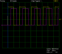
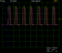
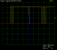
The actual behaviour is rather odd. According to the datasheet, the clock in bitbang mode is 16 times the specified baud rate. And the 8 bits in each byte are sent to 8 different pins at the same time, as parallel output. If I set the baud rate to 300, I expect it to be really 4800, so 200us per tick. However, the scope trace shows bursts of 50us bits with delays in between.
The really odd thing is that the average transfer rate was as expected for each of the baud rates I tried. The ftdi_write_data function blocks when the buffer is full; and when trying to send 100000 bytes for a test, it took the expected amount of time to return (for example, 20 seconds to execute with 100000 bytes at "300 baud"). Also, in UART mode, the output doesn't normally have gaps between the bytes.

I would have thought I must be doing something silly here, but it sounds like the author of the Hackaday article has the same problem.
Code:
#include <stdio.h>
#include <ftdi.h>

#define LED1 0x08  /* CTS (brown wire on FTDI cable) */
#define LED2 0x01  /* TX  (orange) */
#define LED3 0x02  /* RX  (yellow) */
#define LED4 0x14  /* RTS (green on FTDI) + DTR (on SparkFun breakout) */

#define BUFLEN 100000

int main() {
    int i,n;
    struct ftdi_context ftdic;
    unsigned char data[BUFLEN];

    for (i = 0; i < BUFLEN; i ++) {
        data[i] = 0;
        if (i % 2 == 0) {
            data[i] = LED1;
        }
    }

    ftdi_init(&ftdic);

    if(ftdi_usb_open(&ftdic, 0x0403, 0x6001) < 0) {
        printf("unable to open device: %s\n", ftdi_get_error_string(&ftdic));
        return 1;
    }
    
    if (ftdi_set_bitmode(&ftdic, LED1 | LED2 | LED3 | LED4, BITMODE_BITBANG)) {
        printf("unable to set bit mode: %s\n", ftdi_get_error_string(&ftdic));
        return 1;
    }

    if (ftdi_set_baudrate(&ftdic, 300)) {
        printf("unable to set baud rate: %s\n", ftdi_get_error_string(&ftdic));
        return 1;
    }

    for(;;) {
        puts(".");
        ftdi_write_data(&ftdic, data, BUFLEN);
    }
}
ftdi_b300.png
 
Last edited:
That trace looks like '..' to me. No pauses, but a 0x2 followed by an 0xe, twice, logic high. I can't comment on the bit rate, as I don't really understand your oscilloscope timings. Does the T/div refer to the big grid lines visible (in which case the bits are taking roughly 40us) or does it refer to the little ticks visible on the horizontal axis, which would make the bits take the expected 200us give or take?


Edit: Sorry, looking at it again I'm not sure about that 0x2e. Is that the start of the trace? If it were 2e I'd expect one byte to be mostly low and one to be mostly high, or if it were doing rising edge for logic 1 it would be busy for the e byte, and it's showing neither of those tendencies. I'll need to look again at it with fresh eyes.
 
Last edited by a moderator:
The T/div is the grid lines, so 200us T/div would be 40us for a small tick.

That's a trace from some point during the run of the program, which is supposed to be outputting a regular square wave with a half-period of 208us. Instead it's outputting a rather irregular square wave with a long-term average frequency very close to the expected value.
 
Ah yes. Sorry, I had your C code completely arse about tit. I follow it now.


I'm out of my depth here, so I'm just throwing ideas out and seeing what sticks really, but if you'll forgive me perhaps what you're seeing is a PWM encoded version of a square wave, with the pulses being on a non-multiple of your baud rate?
 
Hmm, maybe non-multiples has something to do with it.

Code:
#include <stdio.h>
#include <ftdi.h>

#define LED1 0x08  /* CTS (brown wire on FTDI cable) */
#define LED2 0x01  /* TX  (orange) */
#define LED3 0x02  /* RX  (yellow) */
#define LED4 0x14  /* RTS (green on FTDI) + DTR (on SparkFun breakout) */

#define BUFLEN 100

int main() {
    int i;
    struct ftdi_context ftdic;
    unsigned char data[BUFLEN];

    for (i = 0; i < BUFLEN; i ++) {
        switch (i % 4) {
            case 0: data[i] = LED1;        break;
            case 1: data[i] = LED1 | LED2; break;
            case 2: data[i] = LED2;        break;
            case 3: data[i] = 0;           break;
        }
    }

    ftdi_init(&ftdic);

    if(ftdi_usb_open(&ftdic, 0x0403, 0x6001) < 0) {
        printf("unable to open device: %s\n", ftdi_get_error_string(&ftdic));
        return 1;
    }
    
    if (ftdi_set_bitmode(&ftdic, LED1 | LED2 | LED3 | LED4, BITMODE_BITBANG)) {
        printf("unable to set bit mode: %s\n", ftdi_get_error_string(&ftdic));
        return 1;
    }

    if (ftdi_set_baudrate(&ftdic, 1200)) {
        printf("unable to set baud rate: %s\n", ftdi_get_error_string(&ftdic));
        return 1;
    }

    ftdi_write_data(&ftdic, data, BUFLEN);
    return 0;
}
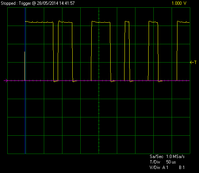
At 1200, this program is behaving correctly (52us bits):
freq3_b1200.png

Setting it to 300 gives some output exactly as above, followed by a long gap, followed by some more output like above. So I guess it doesn't appreciate the number 300.

But changing the program in the OP to 1200 doesn't help (expected 52us bits, got irregular 13us to 80us):

freq1_b1200.png

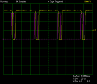
New program at 4800 gives a more regular error (expected 13us bits, got repeating 4us, 4us, 4us, 40us):

freq3_b4800.png

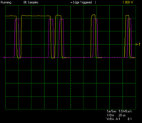
Except when the phase shift of the delays changes:

freq3_b4800_2.png

9600 seems to give a regular error (expected 6us bits, got repeating 4us, 4us, 4us, 12us):

freq3_b9600.png

(I wonder what's up with the voltages. The eBay listing says "This board ship default to 5V, but you can cut the default trace and add a solder jumper if you need to switch to 3.3V." But I guess it's set to 3.3V already...)
 
Last edited:
"What's up with the voltages" is that I had attached LEDs with series 220R, and the data pins are current-limited to 4mA. (I read that this can be changed to 12mA in the EEPROM.) The voltages on the two pins were slightly different because one LED was green and the other red. Without the LEDs, everything is 5V.

It seems that small bursts of data behave more consistently than large ones. And some clock speeds work better than others - asking for 4600 instead of 4800 gave a trace that looked somewhat like what it was supposed to. So I thought I'd just wire up the IR stuff and try it out, because it might be good enough. It worked a couple of times out of a whole load of attempted transmissions. So near and yet so far :(

20140530_132259_crop.jpg
 
At least for the program in first post, the problem is that Linux is not realtime OS and it may switch to some long task anytime, like flushing out SD card buffers, which will make the USB bus/device starved of data. There is also a problem of CPU wakeup latencies, when your program blocks ARM goes to sleep and the wakeup time is in millisecond range (this can be overcome by adding 'nohlt' kernel argument, but pandora will draw lots of power). There could also be driver quality issues, like sleeping too much and sending USB data too late.

You'd have most control of the latency in u-boot, but you won't have most drivers there, although it does have some support for USB.
 
Last edited by a moderator:
Thanks for the info. What you describe definitely fits what I was talking about in the "EXT connector" thread (including nanosleep not doing what it seemed to be offering to do).

With the FTDI bitbang mode, there's still the issue that some of the bits are shorter than they should be. I suppose it could be getting behind, and then making the next few bits shorter to catch up, i.e. going for the correct average frequency as a design decision. But that doesn't explain why the first bit is sometimes too short, e.g. in the 9600 trace I posted above. And the description in the official documentation implies to me that it wouldn't do that.

Any data written to the device in the normal manner will be self-clocked onto the data pins which have been configured as outputs. Each pin can be independently set as an input or an output. The rate that the data is clocked out at is controlled by the Baud rate generator. For the data to change there, has to be new data written and the Baud rate clock has to tick. If no new data is written to the device, the pins will hold the last value written.
At some point, I'll see whether it behaves the same way on Windows with the D2XX driver and library.

The other thing is that in UART mode, it doesn't seem to suffer from this problem. E.g. in Python,

Code:
import serial
ser = serial.Serial("/dev/ttyUSB0", 2000000)
data = "\xf0" * 100000
for i in range(100):
    ser.write(data)
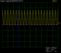
It gives a very stable waveform. I can't be certain there are no gaps, but if there are any, they are uncommon. If the problem with bitbang mode is USB delays, do you know why this would work better? Is there a large buffer on the Pandora side which is still being sent to the USB when my process doesn't have the CPU?
ftdi_uart_2mbit.png
 
Last edited:
It's hard to tell without digging into it, there could be tweaks for serial modes as it's main mode of operation so is likely to be well tuned and tested. It would have to be investigated from the driver side to find what's going on..
 
In the 2Mbaud serial example, there are 10 bits per byte, so the FTDI chip uses 200k bytes per second, and will consume the 128-byte buffer in 640us. Avoiding gaps longer than that in the USB transfer is pretty impressive then...

In the "4800" parallel example, it uses 76800 bytes per second, and will consume the 128-byte buffer in 1.7ms. Sounds like a less-optimized driver might have trouble with that.
 
Back
Top