Zikzak - crummiest 8bit console/computer ever .. but I'm making it!


On the use of different programmers for different chips, just a reminder that an STM32 F4 (in DFU bootloader mode) can easily be programmed by the end user with only a USB cable. You'll need 2 resistors on the DM and DP pins (22 ohms) and GND hooked up to a USB connector. Use dfu-util to upload firmware.

If you add an RS232 chip (or FTDI) on the board, any STM32 (also the F1-F3's) can be programmed through serial.

With jumpers on the right place, the RS232 or FTDI can also be used to program the AVRs if they have a bootloader.

You may not want a bootloader on the AVR (the end user can't do any fancy debugging), just saying in theory it's possible to upload firmware without the use of an external programmer.
 
I'm not too worried about STM programmer .. given the F4 disco with built in st-link is what, $15 or something; but yes, fully agreed, there are workarounds.

--

Whats interesting/weird, is .. I hot-air removed one of the now-questionable ICs from adaptor board, and put my last one in place; went testing the grounds to ensure the orientation is as expected in datasheet (starting to questio if the DS itself is incorrect), and everything seemed good.

Added power, seems fine; PHI (clock out) is showing the clock signal just fine.

So.. 4th one is the charm, but they all looked great solder wise (under microscope even.)

.. I wonder if the first 3 were a bad batch, or did I somehow have the astoundingly poor luck to mis-solder 3 of them, identically, to cause identical failures. It'd be a 1 in 1000 chance to do that I imagine, but .. stranger things have happened.

I dunno.

So, okay, looks like eZ80 is back on the table.

But now I'm sort of interested in the simpler-base option, with pluggable alternative, as above :p hmrf.

Hardware does throw options at you :)

jeff
 
and now broken again! I power cycled a half dozen times before breaking for lunch, the thing worked fine. Left it off, come back after lunch, and now its all shorted. This makes no sense! I must have a mouse that comes in and fries eZ80s when I'm not watching!?!?

I just don't get it.. wtf could cause this, 4 times?!

These chips must be flawed.

jeff
 
... doh, then again.. on most ICs I put decoupling caps across +/-, but this time I forgot. Frak, that could be it.

Maybe, just maybe, the time sI didn't check for power spikes they actually did spike (haha, Murphy hates me), and if I've forgotten caps, maybe it caused some problem there.

Dammn; thats unlikely, but could well be. The avr on the same board does have the decoupling caps.

Shitfucks, I bet thats it.

jeff
 
aaag, I think narrowing in..

If I leave it (the PS) off about 15 minutes and fire it up, it is spitting out 10V for a moment before cutting back to 3.2V.

If I toggle it on/off with only a few seconds, its not doing this spike.

This would have masked my catching it (its a reasonably new addition to my bench), since I checked the output V while using it.

Also..

- normally I run through a regulator

- normally I put the caps across all power pairs

This time.. neither of those. I trusted the PS and was having it spit out the 5V and 3V, and just plain forgot to put the caps across Vss/Vdd (doh.)

I'll have to read up a bit but..

- Do I always need a regulator, to be safe?

- Or do caps across Vdd/Vss cover that? (I normally use .1uF mono .. picked up a roll of 100 of those cheap one day.)

Or do I need some sophisticated 'choke' or something that I can put inline of the + lines on this sucker, for all future?

Will mull that a moment. I bet this is clearly it. The avr's always had better PS fed into then, and have generally had caps.

I think I want to smash this power supply, that just cost me about $100 .. (zilog programmer, 4 eZ80s, 2 of the fancy pricey adapters.)

LESSON LEARNED. *rage*

jeff
 
Screw it.. ordered a few more eZ80s; $4 each and I really want to know if this was the screwup.

Going to build a nice voltage regulator board for 5V + 3V outputs.. right now I only have one for 5V. Since I need to have it on the main pcb anyway, better get it sorted out now, right?

jeff
 
alright, back in business..

- Thief 4 is pretty good; not ideal, but not as bad as reviews would place it

- Eagle 'free' sort of stinks; most people pirate it, but I don't really like doing that.. got a bonus at work, bought Eagle Hobby edition. I must be serious about this hobby.

- got a few more eZ80s in .. Digikey is freaky awesome; ordered 11pm, showed up 11am .. from another country :) (Minnesota is not too far, but still.. across the border!)

I've breadboarded up a couple regulators, so I've got 3.3V and 5V nice and solid, as long as power supply doesn't go totally insane. Never trust bastard power supply :/

next steps..

1) resolder new eZ80 onto adaptor; hard to clean them off (already soldered them a couple times), but hot air helps; lifted off a couple pin contacts (sigh), but hopefully pins I don't need, and maybe I can recover them. Thank god for usb microscope!

--> if they don't blow up after a hour, I'll be impressed ;) pretty certain past issues were my apparently lame power supply, so should be cool

ii) make pcb design for cart; the edge connectors I plan to use showed up the other day (4 of them .. pricey beggars, at $4ea since getting them from the UK; cheaper if I get ones with 'flat contacts' that you bend over, but going to try to use the through-hole ones.) So should be able to make up a template cart .. like a perfboard for cart :) then order some pcbs, and stick a eeprom on there.. should be awesome, and get me some practice laying out pcb and making up parts

iii) start nailing down the final schematic ... I'm liking the sound of that. I'm sure there will be many more revisions since I'm a noob, and will probably screw up the pcb layout a few times, but such is life. Still, eZ80 + stm32 should be fun, and worst case.. can back up onto an avr8-or-two as brain (see blog post)

iv) start making pcb design, woowoo!

.. and play Thief 4 if I can .. I tend to work on my geek hobbies more than game.. too much fun.. but I need to learn to relax. As much as one can relax at midnight/1am after getting screamy babies to sleep :p

jeff
 
Eagle 'free' sort of stinks; most people pirate it, but I don't really like doing that.. got a bonus at work, bought Eagle Hobby edition. I must be serious about this hobby.
Eagle free is okay for "small" 2 layer boards. If you want to make more complex boards with more layers and/or boards larger than 10*8cm, the only solutions are either using another tool to design your board or paying for eagle.
That reminds me that I still have a few PCB to design :

- AMS hall effect joystick

- stereo 8910 audio board (should also make it compatible with 8912) with a stereo jack

- AS1130 led matrix

I just got my set of 60 cristal oscillators. Some pins are a bit bent, but they look ok otherwise. We'll see if they're accurate :p
 
Last edited by a moderator:
I torched another eZ80 .. this TI voltage regulator behaving a little funny (definately needs a tant cap on the output regulation, thats for sure :) .. but these eZ80's just look like if you sneeze at them, they pop; this one is same batch as the others I think .. all from Dec 2008. I think I can get them running, but they must have some huge problem with static or even slight power supply fluctuations .. so I dunno. I really like the featureset, but perhaps for home labs they're not suitable, or I'm having the absolute worst streak of bad luck.

Really bugging me .. _never_ had such a problem with any other chip, and I reall ylike the specs on this sucker. But I steered clear for a year, so probably the best plan is to keep steering away .. but damnit :)

I don't havbe to decide for another few days, but I think I'm going to design away (for the default) from eZ80 .. make it so I can support avr, or z180, or even stm32 as cpu, and then can drop in eZ80 later on the header pins if we like, or redesign that part of pcb. But damnit, the eZ80 would slip in so nicely..

---> of course, we could just run single chip .. zik zak would be much easier to just use the stm32 as the whole machine but thats no fun.. I want it to have some complexity, some crazy fun in there, otherwise.. whats the point? :)

--

You're probably okay on the crystals; they're pirate wet dream in a way though .. you can't just test them with an oscope probe, as it throws them off; and they need extra circuitry to read (unlike an oscilator.) So really, they could put any damned thing in there.. but so far in my experience.. I bought a bunch from ebay etc, and no problem yet! :)

--

That AMS joystick is totally slick; whenever I start making a handheld unit, I'm on those :)

I sort of want to make a LED cube, like a 16x16x16 or something, but man that'd be tedious to build :eek:
 
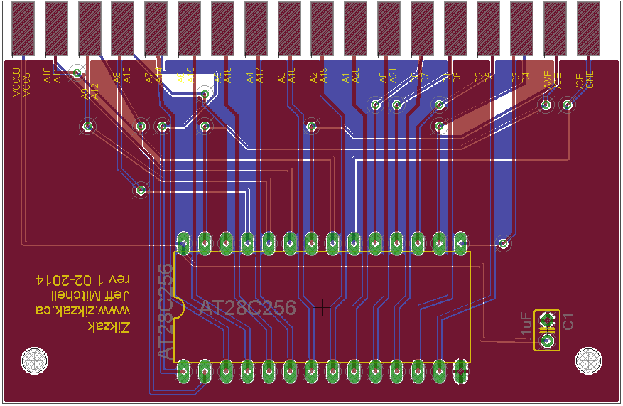
OKay, here is first draft of cartridge slot layout.

I didn't try to make anything fancy so if you insert it backwards, it'll probably catch fire :eek:

I did only think about it a bit .. ie: for the AT28C256 (32KB) eeprom that I intend to use for my own few carts, the pinout should make it easier to do; but for larger eeproms or roms or whatever, the pinout will obviously vary, but there is plenty of space in there; if you want to put it into a cart case, then the Atari 2600 wider carts should accomodate and provide plenty of routing space.

Board won't let me use colours or embed or anything suddenly .. weird; okay, click the link yourself :)

https://raw.github.com/skeezix/zikzak/master/zikcart/protocard_2x18/pinout.png

Let me know if you think this is stupid or not..

I did go for..

- 5V on bottom (through-hole parts can get it easily)

- 3.3V on top (smt parts can get it easily)

- ppower on left, gnd on right

- includes /CE even though likely not used

- Addresses on left

- Data on right

- least-significant-bits for address and data both on top, so easier to probe the stuff that changes more (the low-end address increment for instance)

Will suck to probe with a logic analyser etc though, with two sided stuff; need to add a header for that....

jeff
 
And first cut at cart schematic:

https://raw.github.com/skeezix/zikzak/master/zikcart/protocard_2x18/zikcart/zikcart-2x18-001.png

And just started the pcb layout .. which is to say, I didn't lay anything out, but I did draw and position the pads, and build a good DIP package I believe :p Near a printer tomorrow, so might as well try to print it out and line it up to my edge connector when I get home, see if its remotely right :)

Board: https://raw.github.com/skeezix/zikzak/master/zikcart/protocard_2x18/zikcart/zikcart-2x18-001-brd.png

Note that for the 'fingerboard' part of the edge connector (male side on cart), I made a new component .. two pads, one on top and one on bottom; you can see in schematic where I put the pad tooth with a top and bot pin, and then on the board side you can only see the red (top) pads. For making the board I'm going to follow the Atari-cart style of doing the over/under connections.. pretty slick.

Anyway, too many sleepless nights.. going to bed by 1:30am ('early') tonight, have to drive a few hours tomorrow .. only got about 4-5 hours sleep each of the last couple nights.. eep!

jeff
 
Board exported image is updated .. this is my first routing job, as you can tell by too many vias; I tried to line most of them up nicely so they're not all over the damned place, but a couple are in really goofy spots (too near the 'finger' teeth of the cart.) But hey, first time, what can I say? :) If only I'd left room to label what each finger is ..

https://raw.github.com/skeezix/zikzak/master/zikcart/protocard_2x18/zikcart/zikcart-2x18-001-brd.png

(same as above)

(I wonder why the board won't let me use any bold, etc .. all greyed out)

Anyway, 'gerbv' looks reasonable except text flies off the side .. not sure if thats a gerbv or eagle bug. Whatever :p Its late (again), so I'll check it out tomorrow .. need to pick a studio (seeed, or the two you guys mentioned above), compare costs, see what their design rules are, _etc_. But looks like I may be ready to fire off a cart to get a few printed up .. woot :)

After cart comes back, gotta see if it works at all, etc.. and then time to order the demo parts for the main board (ie: I need to order the bits from digikey say, or buy them locally in enough quantity for a few boards, etc), so I can measure and draw up all the parts I know I can get and need.. not just the 'whatever parts I've got' stuff I've used so far. ie: DC jack, gotta order the one from digikey, since I've only got 2-3 here, and god knows where I got them.. once I have digikey part, I know I can get 'em again likely.. anyway, so once I've got parts, that are replenishable, I can draft the rev1 pcb and get some made for me, and then populate and do actual testing.. and then once it runs some shitty demo on a monitor, see if anyone else actually wants one.

Getting there :)
 
ahh, Ghostery or one of my plugins was hiding some of the buttons, like the bbcode toggle. Theeere we go again ;)
 

zikcart-2x18-001-brd.png


edit: Updated board design a bit .. reduced vertical size, added silkscreens with pin labels, that sort of thing.

I should probably change the top copper pour to be VCC instead of GND (having two GND planes is probably stupid), but I hit send-order anyway :) ($12 for 10 boards, got end of sale :)

At these rates, its pretty crazy .. usual rates for this sort of board (at seeed and elecrow and others I checked) seem to run about $25 + shipping + options; at least at that rate you get your choice of colour.

Still.. at 5cmx5cm to do a QFP adaptor say (no problem), you could fir 2 of those on a 5x10cm deal, or 4 on a 10x10cm deal. If you can do 10cm^2 for $25 + shipping for 10 boards, thats 40 adaptors. Even if you top out and go with FedEx and some options, you're still talking $1.50ea, but most of that is in shipping.

So, yeah, going to do my own adaptors from now on, if the cart comes through ok (and if not, it'll be my own fault for screwing up the board layout or something; live and learn, right?)

jeff
 
Last edited by a moderator:
Wrote up a huge post deciding a bunch of cpu factors, header pins for capes/expansion and part choices, and then Browser Crap went on and it all went away. Ah well :)

But at least Elecrow is on top of their game (they had a sale, went with them instead of seeed and others), and apparently my cart prototypes are ontheir way already! (Order submitted Friday, today is Wednesday.. not too bad.) Since I'm all excited to see how badly I screwed it up, I opted for DHL so at least it'll not take 6 weeks to arrive .. maybe beginning of next week?

RL work totally killing me lately, and the usual super busy at home.. maybe I should take a couple days to 'chill' insomuch as I can; once those babies arrive I'll probably be all fired up again.

In short though .. going to go with on-pcb avr or stm32 for cpu, with full header pins to allow z80, z180, ez80, 6809 or whatever to drop-in as a shield. And given avr has no ram to copy stuff into, is relatively slow, and the ones with XMEM (which is <64KB anyway) are large pincounts, and the DIP40 has only enough pins to run the bus but not talk to peripherals etc.. I basicly have to go with stm32 for cpu. As much as I love avr's, I think the stm32 is better suited.. since I'm pretty used to it, despite its higher complexity; lots of peripherals and a lot of fun to be had in there, with multiple ram banks etc. It can talk via shared memory bus to the gpu, or crazy fast serial, or I2C, etc. Theres a certain symmetry to having two stm32's on there, one as gpu and the other as cpu.. Still aiming for the LQFP64 part but its tempting to go to the 100+ pins and get the FSMC (external memory bus, instead of bitbang and copy to RAM as if bus is a floppy) module .. but with 64pins, shoudl be enough to run the memory bus (30 pins for address+data, plus a couple for control), plus leave say 6 for single joystick, plus a couple for keyboard; still leaves enough pins for another joystick. Want to leave some unassigned, so can drop in SD as expansion later, or a LCD panel.

Will be pretty nifty to make an eZ80 or Z180 expansion :)

(do we call 'em capes or shields or.. zaks!)

..

Given few will have a zikzak, and likely not much software .. one joystick port enough, or shoudl we go two, outright?

jeff
 
Ahh... the waiting. Get some sleep. Best invesment you can do in yourself. I think one joystick could be enough, the other can use the keyboard or a usb joystick?.

But there will always be someone who makes a tron for 2 joysticks. Or that crazy climber that climbed a building where you required 2 joysticks to play...

I remember one joystick port being read before the other one, which meant that you had an unfair advantage depending which port your joystick was connected to in fighting games like International Karate.
 
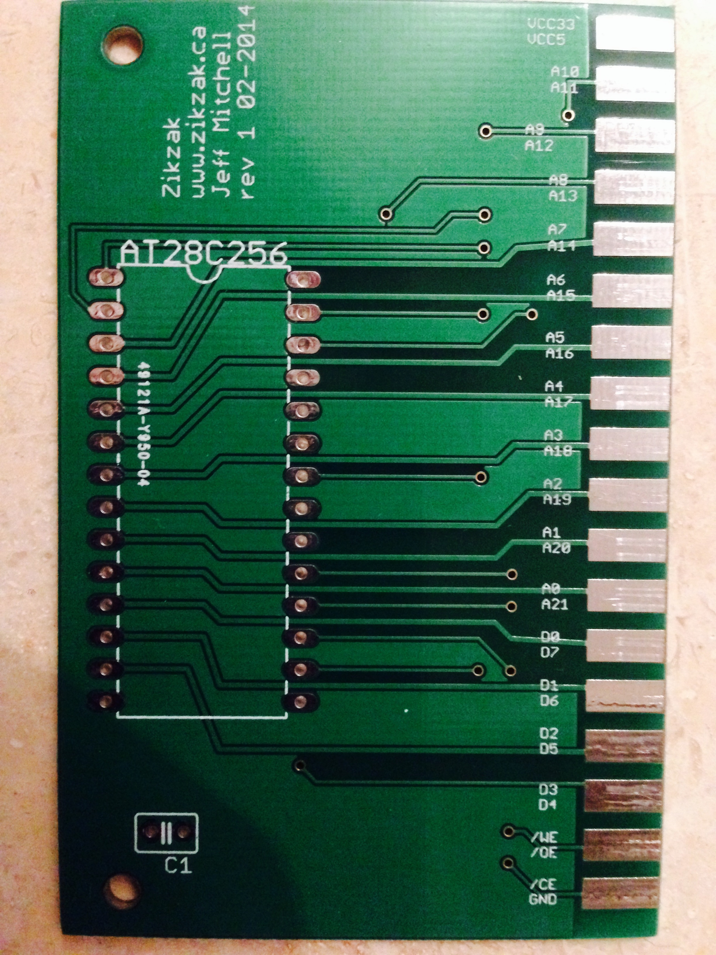
Woowoo, got the first cart prototype from Elecrow! Looks excellent by eye but I need to verify the connections. Think I'll tweak trace sizes (though I had set gnd and power thicker..) but shouldn't matter at my draws..

Check these out :)

https://www.dropbox.com/s/kv4cl8w6pmcd13x/Photo%20Mar%2007%2C%203%2058%2024%20PM.jpg

https://www.dropbox.com/s/vwkwrmwdv3h4ygh/Photo%20Mar%2007%2C%203%2058%2041%20PM.jpg

When I'm near a computer I'll change thise to embedded photo and update blog

edit:

FWIW.. Elecrow was great; they did their job quickly (took only 2-3 business days), and DHL did their part quick as you'd expect .. so I had the pcb in my hand exactly 1 week after submitting it. (normally I woudln't use fast DHL, but I was excited ;)

As to quality .. only slight issues with it, all my own fault; I think its a tad too thick (1.6mm pcb), but elecrow has an assortment of options; I think they had a 1.5, and did have 1.4 .. I want it medium tight, not loose in there.. as is, its quite a tight fitting. Still, fits into the slot .. so maybe it'd loosen up a bit after use, these being brand new edge connector slots.

I forgot to widen the traces for power lines as noted before, but don't think it'll be a problem at all.

I should've added some more gnd<->gnd via's, to help spread the gnd load, but its not like theres a lot going on here so it won't be a problem.

All told, I think a successful first little pcb; certainly improves my confidence .. I'll definately make my own adapters, and need to finish the re-done zikzak shcematic and get to routing that pcb.. that will be a challenge to do right, for sure!

This sucker is quite pretty imho .. nice and shiny, a nice green, and those edge connector teeth are beautiful and retro; I didn't have them golded, seems unnecessary and a little $$, but it looks so slick. You don't see cartridges much anymore :eek:

This sucker fits nicely into a couple of the Atari 2600 cart cases I have; one thing I should watch for is to make sure theres more blank copper space in the areas I'd expect to have screw holes needing drilling. ie: since expecting to use whatever Atari 2600 carts I can scrounge up (or whatever game system carts..), the holes will vary by cart mount point. So I should leave some more blank space in the right places.. but I need ot get a dozen carts and bust them open to get an idea on tradition (if any) inside. ie: Do Atari (company) carts have same internal layout? Do Activision? Or are they all over the place... Anyway, as is, with the cases I've got here, I can just drill a few holes through pcb and they'd mount just fine.

I'm more concerned about the edge connector on the main zikzak pcb; I've selected ones with holes for nut/bolt mounting; hopefully that, along with solder, will hold it on on good.. but with tight carts, don't want to have hairline cracks appearing in the solder joints and futzing carts. Shoudl bust open an Atari 2600 and see how they mounted their slot connectors.. (ie: one idea is just to put a piece of wood or something on the bottom of the pcb and screw into that, for super strength :p ) I'm looking to use throughj-hole edge connector females, but could use the ones where you dead-bug out the pins (arcade style) on the top of the pcb.. so I hope to remember to leave a lot of space around the slot, so that I can put both through-hole and dead-bug traces there, in case I need to switch connectors or if one rips off; the dead-bug connectors are more available and cheaper as well, but through-hole seemed nicer overall.. just rarer. We'll see when I start assembling..

jeff

Image turns out huuge, so spoiler-hid it; take a peek or click above. Its actually credit card sized, not very enormous as the pictures suggest :)

rev1-top.jpg
 
Last edited by a moderator:
Ahh... the waiting. Get some sleep. Best invesment you can do in yourself. I think one joystick could be enough, the other can use the keyboard or a usb joystick?.

But there will always be someone who makes a tron for 2 joysticks. Or that crazy climber that climbed a building where you required 2 joysticks to play...

I remember one joystick port being read before the other one, which meant that you had an unfair advantage depending which port your joystick was connected to in fighting games like International Karate.
I'm not planning on supporting usb out of the box, but its certainly doable; there are usb emulation libraries for bitbanging, and these cpus I'm using are pretty sweet.. probabyl support it handily out of the box. If I've got the extra pins, I'll hook up a second joystick anyway, but you could of course use the pins for whatever... I'll put most of them up on headers :)

Thats a pretty crazy story about port ordering.. I could vaguely see it, but it just can't be true ;) ie: If its reading alternating sticks each frame say, it'd work.. but be odd; reading a stick is so trivial, you'd think they'd do both in a row, same time; but perhaps the effect of the stick is only applied sequentially once per frame or something.. who knows. Sick :)

jeff
 
About your post on the developer blog, you said that the cards are hard to plug in the slot. I had the same problem when I changed the cartridge connector for a brand new one in my NES, you probably just have to break in the slot ;)

I'm still waiting the breakout boards for the STM chips I have. I hope to get them soon…

If I get some extra money in (which I should soon), I'll re-work the SNES+ PanelBoard and get some of those pcb produced.

I've finally started designing the led matrix pcb for the AS1130. I'm just unsure which type of leds/resistors/capacitors I'm going to use… SMC ones would allow me to have a higher DPI "screen", but are a bit harder to get soldered (I wish I had a reflow oven and an automated components positioning robot :p ).

---

I've started talking about making games with a friend, he seems rather interested. So we're currently writing some games ideas on paper :p Next week, we'll choose one of the most simple idea and get started with it!

He is a total noob at writing code, so I'll have to teach him the basics. What I've always found interesting, when trying to teach something to people, is that it really shows what you understood or not. I found it a good way to improve myself.

His skills are that he has really good grasp of many games rules (pen & paper RPG, cards games like magic, etc.), he has mastered self-made scenarios for various pen & paper RPG. And he can keep me motivated :D Fucking awesome skill IMHO!
 
Maybe he doesn't need to 'code' ... Scripting up events using in-game code, or mission/level making ...


I've made a few engines but actually making comtent is time consuming and not my cup of tea.. Hook him :)
 
Back
Top