Zikzak - crummiest 8bit console/computer ever .. but I'm making it!


Msrch break/hellweak, and damaged myself a few ways .. No progress for me lately . I need to cad up lots of parts and start acquiring parts like on/off switches to cad up .. Breadboard or perfboard is one thing but designing a pcb means exact parts .. Huge drag :/
 
Maybe he doesn't need to 'code' ... Scripting up events using in-game code, or mission/level making ...

I've made a few engines but actually making comtent is time consuming and not my cup of tea.. Hook him :)
Well, he wants to learn programming and I want to try teaching (even if I'm not great at programming since my experience is limited).And since he always wanted to learn, but never found the motivation to do it alone, I think it's a good opportunity. ;)

----

I should receive the LQFP32 to DIP adapter soon (end of this month), allowing me to play around with STM8 \o/

(LQFP64 breakout boards should arrive a bit later, then I'll be able to mess with some STM32)

If I get used to STM chips and happy with their features, I'll probably switch to STM family for the elevator project…

The high frequencies chips seems great at handling realtime applications. Moreover they have lots of I/O, lots of integrated peripherals, etc. They really look like beefy little monsters :p

EDIT

I'm currently rethinking the architecture of the elevator… I have to get reliable communications between the various parts of the elevator (mainboard, sensors, displays, buttons etc.).

They can be far away from each others (several meters of cable or even more).

And the communication cables can run near potential EM interferences…

So RS-485 bus could be a good option. It's a linear bus, so I'll probably use two separate buses. One dedicated to sensors and another one dedicated to human/machine interfaces.

If I switch to STM chips, I'll use a STM32 as "main brain". I know it's probably far too much for my needs, but it could allow to add functions later. (well, only if I add some pin headers for unused pins on the mainboard…)

I'll probably have to use "sub brains" to pilot the RS-485 chips and since I don't really want to drag around a ton of programmers, I'd rather use STM8.

I still have to think about all that a bit more! ;)

/EDIT

----

Msrch break/hellweak, and damaged myself a few ways .. No progress for me lately . […]
Take a break while you recover and wait for parts, no hurry :)
 
Last edited by a moderator:
Zikzak as elevator controller!


Fwiw I'll be making an stm32 cpu plugboard for zikzak .. A dip adaptor thats huge and has the caps right on it. ... Naah, be cheaper for you to perfboard one up witha 1.50 futurlec adapter..


In my guthub I've got the minimum wiring diagram .. Lemme know if you need a link


Xbee wireless could work for you too :)
 
Since people are going to use that elevator, I want to make it as safe as possible, so IMHO wireless isn't an option (and it's pricey!).
The main board won't be that far from the electric winch, so I'd rather use a transmission support that won't get completely scrambled when the winch is in function  :D
 
Digging further into EM interference-proof buses, I found the CAN bus. Its hardware implementation is similar to RS-485, but it have it's own communication protocol.
Since it's a standard in the automotive industry, some STM8 (STM8S208 for example) and most of the STM32 have the CAN bus implemented. So those STM just need a transceiver (L9616 from ST, MAX3050, …) wired to their CAN Tx and CAN Rx pins to be ready to rock at 1Mbps (far enough, I'll have at most a few octet to exchange at a time…).
So I'm going to use that CAN bus. (Too bad, ST turned their sample system off for update… I'll have to wait to order the parts)
I just have to rethink everything from scratch… I only done that a bazillion time already  :rolleyes:
 
My latest elevator solution had only one chip (well, a pair of chips, but they work as one…) to poll to get all the possible inputs (buttons and various sensors).
With CAN, I'll have at least 4 slaves modules to which I'll have to push & pull data :
- 3 floor modules. 2 buttons and a simple display (5 leds: one for the 3 levels and two to display which way the elevator is going) piloted by a STM8.
- 1 cabin module. 3 buttons and a fancy display using AS1130 piloted by a STM8
 
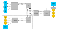
elevator.png
Something like that ^
Now I just need to think the software to make it work perfectly…
 
EDIT:
I've been looking at WaveShare Dev Boards with envy, even if they're a bit pricey. They look really nicely engineered and easy to use with breadboards. But I must stand firm and not buy any of those!

Even if the STM8S208 board and the STM32F405 kit are really tempting…  <_<
 
Last edited by a moderator:
The dev b oards from STM themselves are freakishly cheap, but soimgle chip; I mean, those F429 boards are amazing, and what, $20 or $25 or something? Quite a steal really.

avr's and PICs go live easy as pie, taking seconds; the STMs are nearly as good, just so much more powerful it was overwhelming, but pretty easy to work with, so you'll be in heavan. Those suckers are amazingly powerful. I think my 'go to' chips will be avr and stm for awhile .. avr insce just so easy and solid and reliable, and stm if I want any power at all, or have a few minutes for the slightly more involved wiring. (avr's need what, 4 pins only, and they're good to go.)

I'm using F405's quite a bit, they're a great chip, and fairly well priced.

I've not done much with STM8, since avr just seems to fit my bill there better.

I'm tempted to go more smt though .. I don't mind smt mcu's, as they're big and you're done, but I've never yet worked with smt capacitors and resistors.. just so tiny! But given they only have 2 ends, should be pretty easy to solder, so maybe a good thing to do for all those decoupling caps. ie: an avr has a need of only 2, so throughhole a couple .1uF and good to go; but for STM32F429 say, you've got what, like 8 pairs of power pins or something, starts to be a lot of space for the caps :)

My various injuries (no biggy; did somethign to my back and abdomen so had pain sitting or bending, sucked, and then I sliced a finger to the bone, since I'm an idiot.) are clearing up, so I need to get back in the game here; work is insane, but hopefully settle in a few days; picade is working, I just need to reflash to another distro, sort that out. Wish I had a week off to hack on my projects.. can't believe Iv'e been at zikzaak for a year now, and didn't get _that_ far .. damn RL ;)

jeff
 
I bought and received a SMT8 "dev board".

The board has the footprint of a wide DIP32 chip, it has a STM8S003K3, a SWIM connector, an integrated voltage regulator, unpopulated holes for a crystal oscillator and of course two rows of pin headers. Pretty neat IMHO.

I still have to launch windows and install software tools to get started with STM µcontrollers. But I can't be assed right now… I've just started writing fast and dirty code for a game with my friend. (damn, my OOP skills are rusty <_<  ) So I'm focused on that and nothing else :p
 
I need to fiddle more with STM8, but in the 8bit arena seems like I"m married to avr for now :eek: But variety of the spice of life!

I posted a blog entry on the zikzak site, but just waiting on about 17 different parts orders to come in over the next month; I need to CAD them babies up. I am tempted on one hand to just leave piles of pin headers all over the pcb instead of putting VGA ports, PS/2 keyboard ports, audio jacks, _etc_ .. keep size down, and flexible and all that.. but strikes me as sort of lame to have a board with 20 headers on it ;) So .. got orders in for all those jacks, and a bunch of random parts, and CAD them up, and then make the pcb. Also need to play with zener diodes..

You can use a zener as a low-brow voltage 'regulator'.. a voltage capper, really; get a 5.0V zener and if voltage exceeds 5, it goes off the other way; cool. I'm not sure offhand if thats instant or how long it takes, and does it handle the first hit well? I'm trying to guard against my power supplky which does this big spike of voltage right off, for a microsecond, and then stabailezes. I'm planning to drop a 7805 and L78L33 on there to get the two main voltages, so I need to check those too .. if they handle that first spike or pass it on, but if need be could do .. power supply -> jack -> two regulators -> zeners -> rest of circuit; but that might be 'band aid on band aid' .. gotta fiddle and see once parts start showing up.

Thats going to be a bitchin' week or two.. _17_ of those cheapo orders from ebay, a buck or two each; 10 DC jacks, 5 DC male jacks (so I can make a couple test hookups), zeners (340 for $6 I think it was.. wow!), etc and sundry. Wife is going to have a stroke, but its all so cheap :p

... assembled a big cheapo workbench in my 'office' (I liek to think of it as the 'lab', but no full size human skeleton hanging in the corner yet), so now at least a bit more storage and somewhere to put all my tools .. the hot air gun etc takes up space; so put down the workbench, added a anti-static matt covering .. so awesome.

----

OOP is over-rated ;) I find early on, if you over-OOP it, you end up spending 80% of your time working on infrastructure than work, so a week goes by and you've got all these empty class definitions and interfaces; that all pays off a month later, but after a week you've not got too much done, so its depressing ;) (I'm thinking back to once where I was writing a collectible card game style thing.. so I ended up with classes for 'decks' (container really, but with various sorting and reporting and filtering features), and 'card' (an abstract), and then different kinds of card .. mobiles, mana generators, etc, and then futher refined those; and then attribute classes that could instanciate into values in those guys. Ended up with gotta be 20 or so classes all doing stuff, and wedged together.. it was great. But a few days in and you've got all these classes and no actual game. Or you could just start and put up a shitty GUI and get some AI down and have some basic working game in like 3 days, thats ugly as shit, and refine-refine-refine :)

I keep feeling the tug.. get back to one of the games I started last year, that already have working frameworks down.. just need to fill in and prettify etc (especially my multiplayer guantle game, that was working in a lot of ways, if jittery for long distance network play) .. (and also need to read more, and play more games, and and and.. how many lifetimes do we get?)

jeff
 
OOP is over-rated I find early on, if you over-OOP it, you end up spending 80% of your time working on infrastructure than work
I feel that OOP makes dev easier when you're not alone in a project.That way I can work on a class while someone else is working on another without any trouble.

We're starting really small and simple. As time passes, we will make it more and more complex.

I don't want to spend weeks planning classes, header files or whatever else and get no working code done :p

I think that iterative dev is the best when you're a newbie dev and working in small team.

Let's take your magic-like card game as an example.

I'd first start making a simple Card class that stores a name, a description and an illustration.

At first the Deck would be a class with a simple array of Cards (later adding some more functions, variables, etc.).

Once it work, I would extend the Card class with a Land class. That class would define the fact that the card can generate mana when tapped. Since the Land class extends Card, the array of card still works without problem :p

Then a Creature class that extends Card. That class define attack, defense power and price to put in-game.

Etc.
 
Last edited by a moderator:
Fully agree on all points; in that case I was planning ahead a bit, since that distinguish between 'is' and 'has' can be hard to nail, and a real pita down the road.

ie:

.. Land is Mana?

.. Land _has_ Mana?

I aborted that one before I got anywhere, but I was in the end thinking about an abstract class Attribute, which was inherited /extended into such things as Mana or Effects or whatever, so a Land could have many attributes without inheriting 50 different parent classes. But it depends on your style really .. and language of course, since python and C++ can do multi inheritence, but Java cannot.

Good times. . you're not helping me keep hardware focused with this software chatter ;) Monkeys on the back!

And apparentyl we're both ex-MtG nerds (though in my case, it was about 17 years ago I played my last game; I sold most of my stuff in '99 to help pay for my wedding (I was in very early, so had some valuable stuff); I ended up giving away most stuff to my nephew a few years ago, whatever was left.. but kept one little deckbox that had some of my favorite art and cards; I stumbled across it just the other day and went looking up prices.. if not touched in nearly 20 years, should probably sell it and see if the $$ can help with more current interests, as much as it pains my retrobrain; turns out, if my cards are in peak, they'd still be worth $3500 or so for the top few dozen cards. They're not mint, but not that bad either, so I best pursue .. if I can get $2k, thats a hell of a lot of pressure off for Zikzak parts, as I'm piss broke right now ;)

jeff
 
Fully agree on all points; in that case I was planning ahead a bit, since that distinguish between 'is' and 'has' can be hard to nail, and a real pita down the road.
100% agree… I think that in "card trading" games it's even more complicated than in other kind of games.
I aborted that one before I got anywhere, but I was in the end thinking about an abstract class Attribute, which was inherited /extended into such things as Mana or Effects or whatever, so a Land could have many attributes without inheriting 50 different parent classes. But it depends on your style really .. and language of course, since python and C++ can do multi inheritence, but Java cannot.
That's why we're not planning on the long term right now, we go for the fastest implementation. Getting thing done quick and dirty keep our motivation high, since we can see some results!We're using a language called Haxe, I've been wanting doing some dev with it for ages. A class can inherits (extends) only one class, but it can implements multiple interfaces, much like Java.

Good times. . you're not helping me keep hardware focused with this software chatter ;) Monkeys on the back!
Sorry about that :p
And apparentyl we're both ex-MtG nerds (though in my case, it was about 17 years ago I played my last game;[…]
Yeah I played a bit long ago and stopped at more or less the same time than you. I never had many cards, just a bunch of starter decks and cards that my brother gave me when he made my first deck ever :p I guess a few of those cards could hit the 10$ price… at most.
 
Think I sorted out my power supply ..

I've been planning for awhile to feed the 5V rails from a 7805.. good, reliable solid technology, and cheap as dirt; a lot of the newer LDO regulators are mosfet based and sdeem to die if you look at them funny.. ie: the beautiful little TI TPS7133QP PDIP for instance, is a pretty ncie little chip.. but it caps at 10V; you pass 10V and poof, it goes hot and shorts internally. A 7805 takes anything based about 8V and gives oyu 5.. the more you put in, the hotter it gets until melt down, but it delivers 5 till then; it can take a beating.. 20V or something, and a big ass heatsink,m good to go. (Yes a switching regulator doesn't make heat, but I'm a touch worried they ripple a bit.. add some caps, probably fine; maybe a coil, a friend suggests.. ) .. anywaym, 7805 is tough, I like it.

(I should concern myself with component size .. go surface mount and small size items, but I'm stll trying to stick with DIP and SOIC where possible etc, keep things easy to work with; next project I'll shrink more, but I want zikzak nice and easy to work with, easily hacked and modded and repaired)

My PSU seems to send 10.1V for a brief instant on powerup, and that kills the TPS7133 .. damnit! :) So I've been looking at options to handle that; I'm sort of assuming a 9V power brick is a common zikzak power source, and assuming it'll have a similar risk of spike on startup; so I've been thinking of tossing in a 9V zener (say) up front to trim off some of that potential excess voltage or other tricks, as I kept thinking I was feeding that raw power into the 7805 to get 5V, and also into 7133QP or L78L33 to get the 3.3V out.

(Problem with L78L33 is 100mA limit current .. and the STM32F4 eats up to 93mA at full consumption; I'm not driving it full, and not using many GPIOs, but still.. dont' want to brownout at the wrong times, either.) So L78L33 probably out, despite my getting a 20 pack of them coming from china in a few weeks for a buck :)

So back to TPS7133 .... but had a brainfart _duh_ moment today; 7133 can take 2-10V and deliver 3.3out; for some reason I didn't see I could feed it low volts .. (I wonder if it upscales from 2 to 3.3? one would think from the basic datasheet..) -- anyway, so I have a solid 5V from the 7805, so I can just drive the TPS7133 from the 7805, and voila .. stable 5V rail, and fork off the side to get the 3.3V rail. Seems to run great on breadboard, with the 7805 aned caps taking that initial spike from the bench power supply no problem.

I've got DC jacks in the pipe from china (and a pile of other little bits, see the zikzak site blog podt a week back); right off though, power section is DC jack, couple LEDs, couple caps and resistors, and the TPS7133 with its two caps. Thats not a lot of stuff, but with through hole components, thats a good square inch or square 1.5" of space used up, and not even gotten anywhere. I've not worked out it, but I keep fealing like zikzak is going ot be a 6" square board to keep things airy. Elecrow 4" square boards are $15ea or $25 for 5 of them. 6"x6" works out like $70 for 5 of them.. big jump there. So I shall endeaver to maek 4"x4" board, or maybe 4"x6" or something.

Zikzak is currently planned to actually be two boards .. the base board which is RAM, cart slot for ROM, IO chip (avr probably) and the STM32F4 (or F2) for GPU, plus all the supporting stuff (on/off toggle for power, ps/2 keyb jack, etc etc) and a big pile of headers all over it, including the cpu-board header ('shield' style.) Then the cpu board which will be one of those credit card sized pcbs, including its own decoupling caps and any extra pins it may need. (ie: anything not used by zikzak can have its own headers on the cpu board, so you can jumper off to use them.)

cpu board figuring to be avr8 for simple testing of the zikzak main board, and it'll be able to run gamesd or whatyever of course; and eZ80 cpu board for awesomeness; and stm32 cpu board for supwer power.. dual 186MHz ARM chips would be monsters ..

Good times...

Just waiting for all those jacks and bits to show up so I can measure them and make the CAD bits.

jeff
 
RL is exceedingly busy, but I'm catching up. Tax time too, bleh.

Trying to cut costs as well.. convert from POTs to VOIP, that sort of thing. Single income with 3 kids is rough :)

Still waiting for all those parts from around the world.. probably 3 weeks to go.. so I'm not in a rush right now, but am working on the re-doing-schematic and all that. Little steps like retesting my power approach and schematicing that down, and fiddlign with some ideas.

ie: It is tempting to try to make the cpu pcb dual sided .. ie: one side allow for avr8, the other ez80, that sort of thing. But it makes the pcb layout pretty tricky when you want to run tracesd all around, without being able to jump sides as easy workarounds; end up interleaving up/down/up/down a lot, which is fine but goofy. Still, if I can make it work easily, may do it.. otherwise just one cpu board per cpu, is okay too. They're $15 for 10, so big woop..

jeff
 
Few little packages showed up today (pretty fast.. 2 week turnover; must be the HK ones, they're often pretty quick.)

3.5mm headphone jacks

DC jacks (too small, really tiny little mouth on them; will order some more standard larger ones..)

340 assorted zener diodes (34 values * 10ea, good for prototyping.) But I mean, it was like $6 for 340, just crazy :)

3 different kinds of toggle switches, various sizes and footprints. I'll use these for onboard power switch.

I assembled a metal workbench in beside my office-desk that I've been doing my hacking on the last few years; an office desk with multiple PCS and lights and solder gear etc doesnm't leave a lot of room, especially when it comes to the robot car. But having a metal workbench with nice shelving and such inside.. like the kind of toolchest you see, but a bench format, but super cheap. My basement 'office' is totally awesome. Just need to have arms hanging from the ceiling full of gear :)

jeff
 
Sorry for lack of updates in quite some time .. lost about a month here :/

Real life has been really kicking my butt, but hopefully that will stop in about 2 more weeks; I've got most of the parts here (and really really tempted to buy a 3d printer after selling some old junk :p ). I've been such a tired out wreck, that I've bene playing Hearthstone a bit lately too, which is bad bad bad :) Still, I've started on somie of the schematic redo work (just preliminary), and built up some of my workspace a bit (got a new bench put together, cabling all done etc).

Gorramn I wish I had more free time!

Anyway, Zikzak is still one of my topmost priorities, I just haven't had time lately.
 
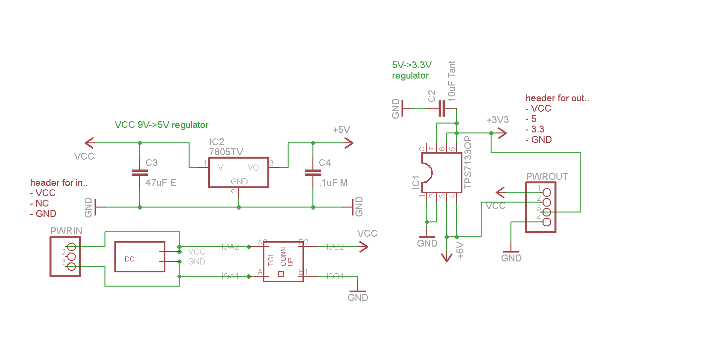
Here is the power schematic; not really complicated at all, but a vital piece to get nailed down.

As you can see.. can take a DC jack or a pin header, to feed in VCC (say 9V + GND is ideal.) This feeds through two regulators and spits out (also via pinheader, or direct to rest of pcb) VCC, 5V, 3.3V, and GND.

This uses the 7805 good old reliable xV->5V regulator, which is a tough little guy; if you go higher, it just makes heat, and it can take spontaneous hits from a goofy power supply without worry. A switching regulator is more efficient and doens't have heat problems, so if we start drawing a full amp out of this guy it'll need a huge heatsink.. but we shouldn't exceed 1/3rd or 1/2 amp here.

Using a really nice little chip, the TPS7133 for the 5V->3.3V regulation, because I love TI and they sent me samples :) (and its in DIP form as well, so at least the power section is nice and simple.)

I've also got toggle-switch (up/down plunger that locks into position) for on/off.

...

I'm tempted to make a little credit card sized PCB of this alone, just because its cheap to knock that size out (10 for $10) and it'd be a nice and easy component to test on its own, and be useful in other projects. And it'd feel like progress to get something in the mail :)

jeff

zik80-base-pwr-001.png
 
I keep waffling (eternally) on going with many little boards (up front) and then making a big all in one, or just go right for all in one to start with. ie: Its not 'done' until its one big board, so .. could just target that and go. But theres some risk there, since its a fairly complex board, and thus harder to isolate components and test..and also fairly expensive to make.

But making a cpu board, a base board, a gpu board, and a power board.. reusable with other projects, cheap to make, easy to test each piece separately.. just goofy to hook together with ribbons, and that can introduce its own issues with transmission noise or funky connections. It is tempting to make the ltitle guys cheap, hook them all up, fiddle around, and once good, copy/paste into one big board and re-route it all. Hmmmm.

Today I'm leanign towards a bvunch of cheap little reusable boards. Tomorrow, maybe one big one. Argh :)

Be be fun to do little boards.. easy to design, send them out to be made, and fn to test. Sounds satisfying and 'feel productive' to keep movement going on, without being stuck in 'big board design hell' .. routing the sucker is hell :)
 
Ha! The infinite looping :)

I can spend months going back and forth between possibility A and possibility B. Then, 1 week after totally going for decision B, possibility C comes up.

Sigh...
 
yep :)

I think I'm going to go with a few small boards for now - just "because" and it seems like it might be more fun and productive; these days I'm just not having any free time at all hardly.. but sitting down to a larger piece of work is a little daunting; why not break it up into small managable bits, and knock them out? Shoudl be able to schem out and route the gpu little mini board by itself over a couple nights, send it and the power pcb off in one order, get them both to play with soon. That'll prove that the pcbhouse can do the QFP large pincount okay, give me some fiddle, and 'protocolize' .. nail down exactly how those pieces will be communicating to each other, as discrete units. The only real downsides are i) using long headers with some ribbon cables is dorky, but proven technology; IDE cables etc.. but I worry it could be noisey or goofy.. a lot of solder joints therte; boards jigglgin around etc. But should be fine... and ii) duplication of effort and waste.. making and routing these little guys, is all thrown away once you merge them all into one large pcb.

But who knows the future.. maybe I'll never get around to merging them (hope I do though!), and why worry about duplication.. its not like its wasted, as you use the little guys for testing, and may use them in other projects.. little cpu board for my robot card, etc.. awesome. Put some extra headers on there (optional of course) for all the other pins, could be really handy.. and all those ISP connectors and such, become easier to manage.

On one big board I keep thinking about how to isolate each region, so they can be tested individually _anyway_; add little toggle switches all over so can block power from going from one section to another? transistors and some management protocol so you can ahave the IO CPU turn off all the other guys? Bleh!

If they're separate little boards.. no more problems; hook up the cpu pcb to the cart pcb, and disconnect the other guys.. boom, instant cart flasher.

Dunno; should be goofy but fun?

I'll give it as shot anyway ..

--> thats my thought today :)

edit: ohhh .. theres digital switches; SEL pin for on/off, and just a bunch of in/out pairs that you can have turned on or off; thats really neat. Cheap as dirt, and slightly easier than using a transistor.

jeff

My toggle switches have the 2ins and 2outs, where the switch effects both of them; so in the above schem you will notice I hooked up both Vcc and GND through it, but really only need one to break the circuit.

Should I have both go through it?

Should only Vcc or GND? Which one?

jeff
 
Last edited by a moderator:
Aight, definately going with a few little pcbs. The power schematic above uses the TPS7133QP for the 3.3V line, but that sucker is 500mA only (which is likely enough, but still.) The 7805 upstream is 1A output (and needs a huge-ass heatsink if you do draw 1A..), but it can nonetheless do 1A. (And why aren't I using switching? Cause I ahve like 40 of the 7805's around :)

On my schem for it, I've just copy/pasted the 3.3V regulation chunk, so it has two of it in there. If you want to get another 500mA safely out, just populate that part of the pcb and away you go.. two full power sets coming out of it.

I'll see if I can fit all that onto the tiny little pcbs, but should be okay.

--

Just working out the GPU schematic now.. essentially it'll be an STM32 F2 or F4 board, with break-out headers for all pins, and built in VGA port and the decoupling caps and some headers for the various busses to come in; then can populate it to use i2c, or serial, or full RAM bus .. could be useful for a few projects - easy drop-in VGA output for any project! - and fit all on a little pcb with luck. All thodse headers sure will eat up space.. 4 * 16pin headers for the BoB, the ISP 20 pin header, the power in header, the VGA port, the i2c and serial headers, and the huge one.. RAM: control and flags, address bus, data bus.Thats like 11 or 12 headers plus the actual caps and oscilators on there. Nasty.

jeff
 
Back
Top