This morning I tried shortening the copper cold finger to be 70 x 30 x 0.5mm. This made the heat transfer worse and was back to 1GHz with short bursts of 1.5GHz. Dont shorten the copper!

My thinking was that the CPU isnt at the end of the board and I want to reduce heat transfer to the battery, so a shorter strap seemed sensible. Not enough heat is taken from the CPU now so I'm going back to a 100mm length.

IMG_20210326_121732.jpg
 
I've done a few more experiments.

Heat from CPU board vs direct from original USB tab
I tried insulating the copper strip from the CPU board and instead bridged across to the original USB port copper tab with a few layers of slugs-be-gone. This was useless and only gets 1GHz sustained. The side heatsink stayed cool.
=> This confirms that the heat is mainly from the the back of the CPU board and not the battery!
IMG_20210326_163444.jpg

Thickness
Next I went back to full thermal contact from the cold finger and the CPU board. I varied the thickness of the copper strip. I tried 0.2mm , 0.5mm and 0.75mm strip. The thicker is much better than the thin.

With the thin sheet and a big heatsink (~10 C / W) the cores are mainly at 1GHz with occasinal bursts 1.5GHz.
With the thick sheet and big heatsink I can get continuous 1.5GHz with occasional drops to 1.25GHz for both cores loaded.

With a single core at 100% load I see continuous 1.5GHz with a core temperature of 81C and battery at 44C.
Bash:
while [[ 1 ]]; do
    tbatt=$(sensors bq27421_0-i2c-1-55 | head -n 4 | tail -n 1 | cut -d " " -f 4)
    echo $(cat /sys/class/thermal/thermal_zone0/temp) $tbatt $(cpufreq-info -f);
    sleep 10;
done

With dual core at 100% I see a cycle of 1.5GHz for 40s and 1.25GHz for 20s

Battery Insulation
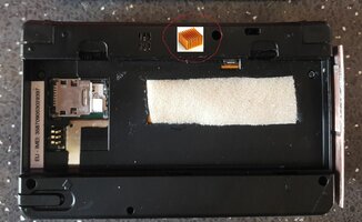
Air is a better insulator than plastic, so I've cut a hole in the pyra case between the battery and the cpu board. I've added a small piece of foam in the hole and another attached to the battery.
IMG_20210326_172345.jpg


The bottom of the pyra is staying cooler and Im not seeing the battery temperature cause throttling during CPU stress testing with a side heatsink attached.
 
Last edited:
I'd expect putting insulation tape on a heatsink would impact it's radiancy, which will also affect convection. But I guess you have the means to test that out. I'd imagine painting it might be better, because we paint our radiators and they still work.
 
The small 10mm high heat sink, now with tape on, is still hot to the touch despite the tape. If it gives a stable pyra that charges whilst coding / browsing then its working fine.

Its been charging fine for the last hour at 1Amp whilst browsing. The battery is holding at 43C as set by evil dragon's thermal governor script:
/usr/share/pyra/scripts/pyra-thermal.sh

If you enjoy late night maths:

Thermal resistance R = thickness / (area x conductivity) [C per watt]
The tape on the 10 x 50mm heat sink is about 0.3mm thick and has conductivity about 0.2 W/m/C
So R = 0.0003 / (0.01 x 0.05 x 0.2 ) = 3 C per watt

The 10 x 50mm flat plate heat sink with natural convection and thermal radiation is about 100 C per watt according to:

So, the tape is worth 3% in terms of thermal resistance. Plastic radiates heat ok, but doesnt conduct so good.
 
This is very interesting. If you find a way to improve the cooling without having such a big strip going outside the case and we can easily add that, I'd do that as improvement when assembling the next Pyras. Please continue your experiments.

The weird thing is though that I tried a metal plate between the battery and CPU board (where you now have the copper) and the result was that the heat didn't go to the heatsink anymore but to the metal plate - thus heating up the battery even more.

How thick is your copper tape?
Why not make the bottom case part out of metal? It'll get a bit warm but the users hands would help move heat away from the CPU and battery. Actually, I think someone else here mentioned this idea before.
 
cool work here!
maybe we can engrave the pyra logo to the sides and by showing our handpalms we let people know what our favourite handheld is.
The safety of this is a good point. The CPU reaches 90C and can brand ARM on my tongue if I lick it, but this is for a tiny surface area.

Im trying to get an area outside of the case as hot as possible and the hottest external temperature I've got so far is ~40C. This is comfortable.

If we could embed the heatsink in the side wall of the case somehow then the <5W wouldn't be that noticeable.
 
Some could design an oven glove that doubles as Pyra sleeve :p
Post automatically merged:

Sorry. I didn't mean to laugh on anyone. I certainly find your research very interesting and thank you for it, @ouzle.
 
Well yes, but could have metal on the sides where hands go.
There is that other idea to make the rear side where the ports are out of metal.
That plate could be removed and replaced by the user then to allow port upgrades (UCB-C for example).

So we might at some point start a case improvement thread before EvilDragon starts with the case revision.
 
So we might at some point start a case improvement thread before EvilDragon starts with the case revision.
Good call, the suggestion to make the rear port surround a metal blanking plate that could possibly be used for heat dissipation, as well as helping make future revisions easier was made in 2016, I believe this was considered too late for any changes to be made, though AFAIK there was no official discussion as to whether this would be achievable or desirable in terms of costs or basic practicality.

So if anyone else has any ideas for case revisions then get them in early.
 
It should be made of programmable matter, obviously.

I'd like an exchangable backplate for better modularity/upgradability and for a thermal solution.
I think to remember though, that ED uttered some worries regarding cooling backplates, that such a thing might be a bit better at relaying mechanical forces to the pcb and the soc than one would wish.
 
The priority for me is to get an air gap between the CPU board and the battery into the case mold. This can then be covered over with the existing sticker and optionally packed with a very open insulating foam. I think this helps with charging the pyra when in use as the battery runs 4 or 5C cooler for equivalent use cases.
 
Hi @ouzle ,
this Thread is very interresting...what if you simply do a bigger Copper Heatsink on Top of the USB Port?
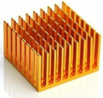
You did a Hole there and maybe a Tiny but more High Raspi Heatsink like this.

I think about making a little bigger Hole over the USB Port too and put a little bigger Heatsink on that.

Ordered an extra Case for Modifications ;)

My Idea is..cooling the USB Port more=cooling the CPU more.
heatsink.jpgheatsink2.jpg
 
Last edited:
Orderes an extra Case for Modifications ;)
Yeah, I hope evildragon orders a few spare cases as chopping them up is a rush!

About putting a bigger heat sink on the cpu to usb heat path: I think we need to work out the thermal resistances for the original cpu board heat spreader and the thermal resistance for the heat sink.....

IMG_20210328_215649.jpg

The cpu board heat spreader is 0.3mm thick copper and 15mm wide, so has a cross-sectional area of A=0.3 x 15 = 4.5mm^2 = 4.5e-6m^2.

It transfers heat a distance of about 20mm = 0.02m.

The thermal conductivity of copper is k=385 W/m/K.

The thermal resistance is given by R = distance / (area x conductivity) = 0.02 / (4.5e-6 * 385) = 12 Celcius per Watt.

The existing heat sink looks to be about 70 C / W judging by the RS catalogue, and if its well attached the the USB port, maybe 50 C / W.

@ingoreis, because the heat spreader is a lower resistance than the heat sink on the usb port, I agree that the heat sink is the bottleneck and we could benefit with a 10C / W heatsink over the USB ports. More air flow would help too.

I've observed that when the CPU is at 90C, the existing heatsink is still just comfortable to hold a finger against. That means the heatsink is ~45C. So, the temperature drop is deltaT= 90-45=45C. With a thermal resistance of 62 C / W, it means we're getting 45 / 62 = 0.7W out of the existing heat sink. The rest of the CPU heat is going into the keyboard (good) and the battery (not good).

But, how much power does the OMAP5 use at full load?
 
The heat path to the keyboard is not as easy as to the battery because the flat bottom of the CPU board is facing the battery, but there's the motherboard PCB and keymat out to the keyboard side

Can we get more conduction to the keyboard side by filling the gap above the CPU chips with something conductive?

EDIT: I've just tried trapping paper between the CPU heatspreader and motherboard and I see it grips the paper, so the chips are in good thermal contact with the motherboard. We should be shifting heat to the keyboard nicely. So why does the bottom of the CPU board get so hot still?
 
Last edited:
Back
Top