Talking to the GPIO's on the EXT-connector


It's probably beyond my level of expertise to set up the GPIO's as interrupts, but it would be nice to know if that is even possible. Is it? The reference manual (warning: 26MB) is going over my head. I can barely understand the Atmel-series of datasheets. Microcontrollers are a lot easier to handle when there's not an OS that "gets in the way".
Yeah it's possible, and instead of fighting the OS you could write a kernel module to handle those interrupts (some C skills required). Otherwise you'd need to patch the bootloader or write your own OS..
I probably should have said: Those microcontrollers are a lot easier to handle when there's not an OS that "gets in the way", referring to the 8-bit AVR-series. They simply execute the few KB of instructions starting at address 0x000 as soon as you power it on. That's the OS. This ARM-thing is a whole different animal, but a kernel module sounds doable. In the somewhat longer term.

Remotely control the Pandora by InfraRed? How would we go about enabling this?
You'd need to find a suitable driver.
I obviously haven't given this infrared thing much thought or research. It's basically bytes over serial. Sweet.


Thanks again!
 
Last edited by a moderator:
Adafruit sells a ready-to-go TXB0108 breakout board for 8 US dollars. The royal You might be interested in that. Also check the App note in the downloads tab. Consider it a TXB0106 with 2 spare parts.


I've made a test setup where a microcontroller on 1.8V acts as the Pandora gpio's that interface with 2 inputs (tactile buttons, 1 pulled up, 1 pulled down), 2 outputs (transistors + LED's), and the UART (generic 5.0V RS232-chip). This all works as expected. It might be the most elaborate and inefficient way to make an LED light up when you press a button, but I wanted to be able to abuse the TXB0106 in the most horrible of ways without it all ending in tears.


In the picture, only the RS232-part of the test-board is used to log in on the Pandora on the PC. That part can be used stand-alone. The microcontroller can also be used stand-alone running on 5V, communicating with and powered by an FTDI USB-cable.
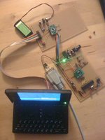

txb0106_3.jpg


I have readings on the voltmeter that don't make sense to me. I can't read the 'transitions' between states reliably. I can measure the pins being HIGH or LOW on both sides of the TXB0106 without problems. It all checks out, and there's nothing wrong with individual 'readings'. However, when I press a button without removing the voltmeter from the pin, the pin 'switches' between 2.25V (LOW) and 2.7V (HIGH) on the 5V side, and between 0.8V and 1.0V on the 1.8V side. When I *do* remove the voltmeter and then measure again, it's back to either 0.0V and 1.8V (or 0.0V and 5.0V) what it should be. The same with outputs.


So as soon as I measure things, it influences the behavior of the TXB0106 and everything goes haywire. When I simply leave it alone and "just use it", everything's OK and hunky-dory and normal and awesome. I can live with that, but understanding it would be better.


I'm not sure what to do with that Output Enable (OE) pin on the TXB0106. When LOW, the rest of the pins are in "high-impedance mode", basically disabling them. It's pulled up to VCCA at the moment, but I think I'd want control over it by a microcontroller or button and have it LOW when it "boots up", pulling it HIGH when everything else is set up. When I attach the battery, I can see 1 LED light up for a short period when it shouldn't. That doesn't happen when OE is LOW during that time. So I'd want to power everything on with OE LOW, then pull it up after a few milliseconds.


If I understand correctly, the TXB0106 has internal 4K pull-up resistors on both sides. You have no control over that, so deal with it if you want to add your own. For inputs, I used 1K pull-down and pull-up on the 5V side, no internal pull-up setup on the microcontroller (read: Pandora). That worked for me. YMMV.
 
Last edited by a moderator:
Once we can talk to a microcontroller over UART, we'll not only have PWM but also ADC, I2C, SPI etcetera, along with a virtually unlimited amount of GPIO's. So no problem there.
smile.gif
Want!


I've been thinking of connecting to an msp430 with an attached lcd-screen and a bunch of potmeters, buttons etc.


What would be needed to get this working, or how far are you with for instance I2C over gpio?
 
I though we had internal I2C in pandoras - why re-implement it over separate GPIOs?
 
Eh, so you don't have to solder separate cables on to the board and stick them out of the case somewhere?


Just using the ext-plug would be a big advantage imo. And if you're not using all the gpio-ports .. why not?
 
Last edited by a moderator:
Ok, I've played around blinking the uart2 pins now (just put a ~50ohm resistor between the led and gnd). Haven't gotten around to disable the uart3 pins as instructed earlier.

For UART3 pins, you need to switch them from uart mode to GPIO mode in pin mux. This would currently require recompiling u-boot, I'll think about including controls for this to next hotfix. Maybe add regulator voltage control too.
@ Notaz: have you worked on this yet?
 
^ how about now? ^_^


I have found some new inspiration to work on a project, but having i2c would be really handy (although I could also do one-wire communication with the msp430, but that is quite slow).
 
It does, the pads are even readily solderable. Just make sure you use different addresses from the nubs and the power control chips.
 
The main reason I don't want to solder directly to the board is that I don't want wires sticking out of my pandora.


And considering we have this wonderfull ext-plug with gpio-pins .. I'd rather use this with a closed cable to whatever hardware I want to control.


It doesn't make any sense to stick some random wires out of the case and completely neglect the ext-port.


There must be a way to bitbang on the gpio-ports somehow then, no?


It would've been way smarter to put i2c on the ext-port. Then you can attach a whole range of devices/externals to it (more i/o, more pwm etc. etc.).
 
Last edited by a moderator:
Wow. Topic still lives. I don't receive emails anymore when someone replies. *clicks 'follow' again*


@dreamer If you let the MSP430 control the display, you might get away with sending simple commands from the Pandora to the MSP430 over UART. Maybe like 'drawRectangle x1 y1 x2 y2', 'drawLine x1 y1 x2 y2', 'drawCircle x y r' or whatever protocol you might think of. Communicating the states of the buttons and potmeters back to the Pandora can also be done over UART. This is how I do it with AVRs, and it works really well. OK, I don't have a screen attached, but the idea is the same.


Bitbanging the GPIO's is also possible of course. Use the /sys/class/gpio interface for this. See script+link in OP.


I would have liked i2c on the ext-port as well, but we'll have to live with what we got.
 
^ ok, I don't know anything about uart. I2C just seemed like a fairly simple (and fast enough) interface to do what I want. And it's easilly extendible to multiple devices on the same bus, which is an advantage.


Btw, the it's a character display, so I just need to send ascii ;)


[Edit: ok, so maybe I can do rs232 over uart .. I'll look in to that as well]
 
Last edited by a moderator:
On an MSP430, look for TXD and RXD pins (P1.1 and P1.2). Those are for UART. You can simply send and receive characters through a terminal emulator (for example screen or minicom). That also makes it even easier to debug than I2C, if I may say so.


I know nothing about MSP430, so you're on your own there, but I'm sure there are lots of code examples on the interweb.


On the pandora, I used this code to communicate with the AVR: http://www.teuniz.net/RS-232/ (but again, simply sending commands in a terminal emulator also works).


Make sure you're using some form of voltage level conversion to go from 3.3 volts on the RXD and TXD pins on the MSP430, to 1.8V on the RXD and TXD pins on the Pandora.
 
ok it turns out it's is possible to change pin functions with 3.2 kernel. Preparation:


Code:
$ sudo su

# mkdir /debug

# mount -t debugfs none /debug


Now to check current pin function, let's take UART2_CTS as an example (pin names are by their primary functions, note that on pandora it's setup as GPIO by default):


Code:
# cat /debug/omap_mux/uart2_rts

name: uart2_rts.gpio_145 (0x48002176/0x146 = 0x010c), b ab25, t NA

mode: OMAP_PIN_INPUT_PULLDOWN | OMAP_MUX_MODE4

signals: uart2_rts | mcbsp3_dr | gpt10_pwm_evt | NA | gpio_145 | NA | NA | safe_mode

OMAP_PIN_INPUT_PULLDOWN tells us that this pin is in input mode and has internal pulldown resistor enabled, and is set to mode4. "signals:" lists 5 modes that this pin supports, the 4th (zero based) is gpio_145, so it's now in GPIO mode.


Now take the magic number 0x010c from 1st line, it's described in chapter 7.4.4 "Pad Functional Multiplexing and Configuration" of OMAP3 TRM (http://www.ti.com/pr...hnicaldocuments). If you look at the figure there you'll see that function is selected by 3 LSB bits, so to switch to UART mode you need mode0, so you change the value to have those bits as 0 and get 0x0108.


Let's get back to the shell:


Code:
# echo 0x0108 > /debug/omap_mux/uart2_rts

# cat /debug/omap_mux/uart2_rts

name: uart2_rts.uart2_rts (0x48002176/0x146 = 0x0108), b ab25, t NA

mode: OMAP_PIN_INPUT_PULLDOWN | OMAP_MUX_MODE0

signals: uart2_rts | mcbsp3_dr | gpt10_pwm_evt | NA | gpio_145 | NA | NA | safe_mode

and here, you have turned it to UART mode. Do this for remaining 3 pins and you should get working UART controlled through /dev/ttyO1 . You can even use hardware flow control (cts/rts).
 
Last edited by a moderator:
That's extremely helpful again, as always. Thank you so much, notaz!


So, just to make sure I understand it correctly, if we were to set gpio pin 144 to 147 in Mode2, as outputs, without pullup or pulldown using this method, it turns them into 4 PWM pins? If so, cool! I know you already said there will probably be trouble with timers, as they will sometimes be in use for other things. But still, that's cool.


Thanks again!
 
Last edited by a moderator:
OK cool :)


I'm personally not planning on doing that, but it's great to know how to poke that register. If only to set the internal pullup or pulldown resistors, not to mention muxmode!


Awesome.
 
Back
Top