EXT Port media controls and buttons


Nardella

Member
Joined
Mar 4, 2011
Messages
352
So we now have ext port connectors available and production of custom cables will start soon. I have three things I would like to see.


A cable that connects to the ext port with a small box on the end of the cable with media keys and a place to plug in some headphones. When plugged in it should disable the speakers.


A small box that plugs into the ext port that has only buttons for media controls (so you can control your media player with the Pandora lid closed (this would have no cable it would just be like an extension of the Pandora).


I also want to build something that would add a second set of shoulder buttons.


We need some kind of standard for how this would be accomplished. We need to be able to make a standard piece of hardware that can have say 10 buttons. And a piece of software that can map those buttons to anything we want.
 
We need some kind of standard for how this would be accomplished. We need to be able to make a standard piece of hardware that can have say 10 buttons. And a piece of software that can map those buttons to anything we want.
6 buttons on the EXT port, but yes, that's a good idea. :)


A simple driver needs to be written for the EXT port, make it easy to set the lines to input, output, or serial communication. When in input, it'd be pretty easy to convert them to keyboard events, similar to how the game buttons are keyboard events.
 
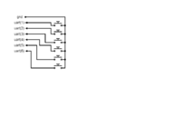
Okay, so what would the schematic look like? We would be best off to have a standardized circuit for a button pad so anyone making an accessory knows what to do. Also want a way for the driver to know that something is plugged into the ext port (to mute speakers).


I suspect that more than 6 buttons will be possible. If you provide an illustration and explanation of what a circuit would look like I should be able to help design something with more buttons without too much complexity.
 
Last edited by a moderator:
I thing, that external controls should be made trough serial communication with some MCU (some tiny AVR or so). This could allow even external display (ie song name, artist name, alarm time...). Opposite to 6 GPIO lines this needs power and it means sucking it from Pandora - we have... (searching) 1.5 to 3.0 V @ 200 mA (or add small battery, like 1xAAA, CR2032, LR44...)
 
I thing, that external controls should be made trough serial communication with some MCU (some tiny AVR or so). This could allow even external display (ie song name, artist name, alarm time...). Opposite to 6 GPIO lines this needs power and it means sucking it from Pandora - we have... (searching) 1.5 to 3.0 V @ 200 mA (or add small battery, like 1xAAA, CR2032, LR44...)
This is what I'm planning to do also. A breakout-box with all A/V and an integrated AVR as a "serial gpio-expander". I have this working as a prototype (with a USB FTDI-cable) on my Pandora. Just waiting for the connectors, and more insight in the voltage-level shifting of the UART. Am I correct in assuming a TXB0104 and a voltage regulator to 1.8 volt (edit: LP2992) is "all" we need?
 
Last edited by a moderator:
1,5 to 3V at 200mA is far enough for most of the low power µcontrollers.


We even talked about a µC developper's kit here on the forum (Texas Instrument MSP430G2xxx LaunchPad) that may be a good candidate.
wink.gif


MSP430 µC are really low power, have a nice "sleeping" mode and really fast to get out of this mode.


A small screen may need a bit more power, I think.
 
Last edited by a moderator:
I stick to AVR :) I was also considering a powered USB-hub inside the box and use 5V from there. It could also power a built in hard disk.


Edit: The ext-port only has a 3 volt line. I believe that at an absolute minimum, we need the TXB0104 and LP2992 anyway, to make sure we don't blow up the 1.8V UART. I would like to know if we can leave out the MAX3381 (obvious link).
 
Last edited by a moderator:
Is there a way to do this without needing some kind of chip or IC?


I mean, would it be possible to create something out of only resistors and switches?
 
Yes, but limited to 6 buttons.


A "simple driver" like WizardStan mentions would be extremely helpful.
 
Last edited by a moderator:
That's how I would also try it, yes. :)


But I said this before and I'll say it again: I'm an idiot. I know nothing.


The schematic assumes the default state of the gpio-'pin' to be 'pulled up'. I think the driver should handle that, but do keep in mind that I know nothing. I would like confirmation on this myself.


Edit: removed some, added some.
 
Last edited by a moderator:
Yes, but limited to 6 buttons.


A "simple driver" like WizardStan mentions would be extremely helpful.

is a remote control possible?

From the Official_Hackers_Manual:

- UART3 can also be configured for IrDA (Infrared Data Association) or CIR (Consumer Infrared Modes)
I don't know what this means exactly, but it could be related. Also, next paragraph:

*** NOTE – All digital pins on this connector are 1.8V logic and must be level shifted if they need to be interfaced to a higher/lower voltage system. Failure to do so could result in permanent damage to these pins on the OMAP3530, rendering them inoperable or even creating a short circuit inside the chip.
 
Back
Top